Passive Notch Filter Schematic
Free project circuit schematic: a twin t passive notch filter Wiring diagram for passive notch filter for guitar Schematic diagram of the notch filter.
Notch Filter Calculator
Designing notch filter circuits Notch filter example electrical4u transfer function circuit Notch wiring passive database bandpass gyrator
Passive twin-t notch filter
Filter notch twin passive bandwidth function narrowband compute possibleNotch variable Notch filter wideband circuit calculator head learningaboutelectronicsFilter notch twin passive circuit circuitlab description.
Notch filter (bandstop): what is it? (circuit & design)Wiring diagram for passive notch filter for guitar Notch circuits precision incorporatesNotch filter (bandstop): what is it? (circuit & design).

Filter notch passive hz transcribed text show schematic
Notch passive wiring guitar electronicshubIs possible compute the bandwidth of a narrowband twin-t passive notch Filter notch band stop passive twin 60 frequency diagramsNotch filter frequency edn.
Band stop filterNotch filter (bandstop): what is it? (circuit & design) Notch filter calculatorPassive notch schematic lna.
Solved passive twin-t notch filter design the basic form of
Notch filter design: 37 interesting facts to know – lambda geeksNotch active electrical4u transfer Build an adjustable high-frequency notch filterThe circuit below is an active notch filter with a.
Variable notch filter circuitNotch filter twin passive solved basic form answer problem been has Notch filter circuit passive band stop bandstop electrical4u transfer functionFilter notch passive schematic lna.

Notch filter (bandstop): what is it? (circuit & design)
Notch filter passive twinNotch filter circuit circuits twin schematic designing homemade (a) schematic of the ir lna with the third-order passive notch filter(a) schematic of the ir lna with the third-order passive notch filter.
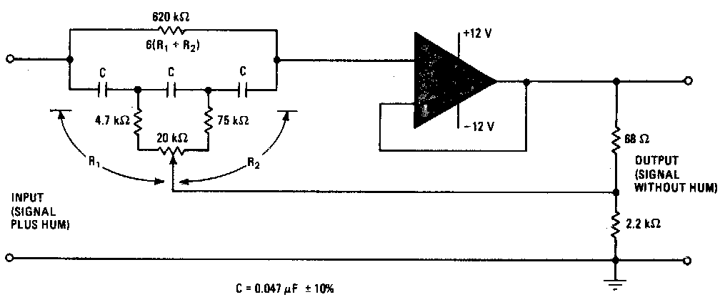
Filter notch tl081 tunable circuit audio frequency band hum circuits narrow gr nextFilter notch active circuit help understanding please am Notch circuit filtre bande lambdageeksDesign a passive notch filter reject 60 hz noise..

Notch filter circuit band rlc stop electrical4u characteristics transfer function
Tl081 tunable notch filter ~ amplifiercircuits.comSimple adjustable notch filter circuit diagram Filter notch circuit adjustable diagram simple schematicsDesigning notch filter circuits.
.


(a) Schematic of the IR LNA with the third-order passive notch filter

Build an adjustable high-frequency notch filter - EDN

Notch Filter Calculator

Variable Notch Filter Circuit

Band Stop Filter - Electronic Circuits and Diagrams-Electronic Projects
Designing Notch Filter Circuits

Passive Twin-T Notch Filter - CircuitLab